
Build yourself a foosball table!
Free 3D CAD files available. 
Some kids never grow up! Yes, I decided to build a foosball table. And I’m happy to report the game action is excellent. Plus we’re having so much fun competing with the grandkids which has been a nice alternative to the video games… which I never win!
Want to build your own?
Here is recap of my foosball project to get you started making your own custom foosball table. I also provided for download my 3D CAD model to support your efforts. Finally, lots of my actual construction details are visible in the provided image gallery.
My Foosball Table Project
My foosball table combines the popular Tornado playing field layout (flat playing field, 3-man goalie) with the more affordable (but excellent quality) Warrior table hardware (14mm solid rods, 2-part bearings, weight balanced men, adjustable feet levelers, playing field side strips). I used modified Warrior 3-man rods (2 new holes in each rod) for the goalie rods. My cabinet design features tournament quality hardware; very sturdy, furniture-quality construction; leg levelers; classic scoring ‘rattler board’; score keepers; and side ball returns. The playing field can also be removed if repairs or replacement are ever needed.
I created my design using a 3D modeling program (Moi3D) and the downloadable files are provided in several common CAD file formats. After my model was completed, I used this model to prepare my parts lists and subsequently purchase my hardware, materials, and supplies. I purchased the Warrior hardware directly from the Warrior website. The other parts, materials, and supplies are all common items readily available from multiple sources.
If you’re interested in building your own table, you’ll first need to decide on a 1-man goalie rod (playing field with corner ramps) or a 3-man goalie rod (flat playing field). Then purchase your rods, rod bearings, bumpers, men, playing field side strips, and leg levelers before starting your build. You’ll need these parts to ensure your design dimensions are correct. My 3D model is dimensioned for a 3-man goalie rod design (Tornado layout), but uses Warrior brand parts.
My foosball table design and construction can be segmented into four main parts.
(1) First I needed to make the playing field with the correct field layout and dimensions.
(2) Next, I needed a cabinet to hold the playing field at the correct height.
(3) The cabinet needed ball returns to move the ball from the playing field goal to the ball return cutouts in the cabinet sides.
(4) Then, I added legs with levelers so I had a level playing field at the correct height above the floor.
Playing Field
Rods and Men
Selecting (1) a 3-man goalie configuration; (2) flat field layout; (3) and the Warrior rods plus men (and leg levelers) were my first major decisions. The playing field layout had to be compatible with these parts. Since Warrior Foosball tables use a 1-man goalie rod, I did purchase and modify two additional Warrior brand 3-man rods. For these two rods, two new holes were drilled in each rod to re-locate the two outer men to match the Tornado 3-man goalie rod spacing.
Playing Field Bottom
I used 3mm clear acrylic, walnut inlays, 1/4″ baltic birch plywood, and 3/4″ MDF for my playing field. I cut the inlay dado cuts for the field layout markings in the 1/4″ plywood using my router. After gluing the walnut inlays and sanding flush with the plywood, the plywood playing field was first finished with several coats of wiping varnish, and then glued to the MDF. The heavy MDF ensured a very flat and rigid base. After spending so much effort to create the inlayed playing field layout, I wanted to protect the inlayed surface. So I ‘sanded’ the 3mm acrylic surface to remove the shiny, slick surface using an orbital sander and 60 grit sanding disc. Spray adhesive was then used to glue the acrylic to the plywood. I should have waited for a drier day to use the spray adhesive. The cold spray condensed some water droplets onto the plywood which left a few small water marks in the finish. After the foosball table was completed including the varnish finish, the adhesive-backed playing field side strips (approx. 0.5mm x 15mm) were added. These thin strips are sized just right so the ball doesn’t get stuck in a dead zone along the side wall.
Overall, I’m very pleased with the finished playing field. The field is perfectly flat and the sanded acrylic provides excellent ball control. If you need a simpler field layout solution, you could simply paint the layout or possibly create and order a graphic overlay. All the playing field dimensions are available in the downloadable 3D model.
Playing Field Goal Ends + Sides
I used 3/4″ baltic birch plywood to make the playing field ends (with goal cutouts) and sides (with rod bearing cutouts). My router with a template bit and template were used to cutout the goal opening in each end. The rod bearing cutouts were made after I glued each playing field side to the matching cabinet side. Once glued together, I was able to accurately mark the rod hole locations and drill the holes using a 42mm hole cutting bit. I also carefully marked and drilled the rod bearing indexing / retaining pin holes (2 for each bearing). The playing field ends were installed after the cabinet sides and playing field were screwed together. If I was going to build another table, I’d consider first building the playing field ‘box’ (bottom+sides+ends) and then mounting the completed box to the cabinet.
Cabinet
My foosball table sits in our family room, so I wanted the table appearance to also be commercial quality. So I selected 3/4″ birch veneer plywood with walnut trim strips. I used 8 coats of wiping varnish (statin) for the finish. The cabinet sides are attached to the playing field using machine screws and threaded brass inserts. I carefully marked and drilled these matching holes to ensure the assembled cabinet was square and the opposing side rod holes were exactly opposite each other. The playing field ends (not cabinet ends) were screwed to the playing field sides (not bottom) now that the cabinet sides were attached to the playing field bottom. Next the cabinet end blocking was glued into place (spacers between the playing field ends and cabinet ends). Then the cabinet ends were glued and screwed to these end blocks and the playing field base was screwed to the cabinet end using the threaded inserts and machine screws. Once assembled, the cabinet was very solid but still allowed removal of the playing field. Now that the cabinet and playing field were assembled, I temporarily installed the rod bearings and rods and detected some turning friction in a few bearings. So I lightly sanded these rod holes to improve the hole alignment so the rods turned easily within the bearings.
I now had the basic cabinet and playing field assembled; verified the playing field dimensions; and tested the rods and bearings. The cabinet walnut trim was not installed until the foosball table was complete and ready for varnishing.
Ball Return
I wanted a scored ball to make the classic ‘rattle’ pop and then return to the correct team. So I needed a capture box with a ‘rattle board’ and a ball return on each cabinet side. (The scored ball returns to the team not scoring the goal.)
The scored ball (1) drops into the capture box bottom; (2) rolls down the sloped ramp connected to the center ramp; (3) and drops onto the correct center ramp where the ball is routed to the cabinet side cutout.
I divided the ball capture and routing into three parts.
(1) Ball Capture Box: First, the scored ball had to be captured after passing into the goal cutout.
(2) Transition Ramp: Route the from the capture box to the cabinet center ramp.
(3) Side Return Ramp: Receive the ball from the transition ramp and route to the cabinet side cutout.
Ball Capture Box
I wanted to hear the classic ‘rattle’ when a scored ball hit the back of the capture box. So I used a simple ‘capture box’ frame with sloped 3/8″ wide dado cuts to hold the sloped 1/4″ baltic birch rattle board. After the scored ball strikes the rattle board, the ball drops vertically to the sloped capture box bottom and then rolls onto the ball return ramp. The capture box is installed from underneath the playing field. Slide the box up through the playing field base cutout and then place the bottom mounting L-bracket into position and secure with machine screws.
Transition Return Ramp
I located the ball return cutouts at the bottom center of each cabinet side so the ball could be easily removed by the correct team. So the transition return ramps had to route the ball from the capture box to bottom center of the cabinet. Each removable transition ramp is installed by resting the wide end of the ramp onto the capture box bottom and resting the smaller ramp assembly end onto the side return ramp that connects the two cabinet sides. So of course the ball capture boxes and side return ramp need to be installed before installing the transition return ramps.
Side Return Ramp
My side return ramp assembly serves a dual purpose. The assembly routes the ball from the transition ramp to the side cutout, plus the assembly connects the two cabinet sides for added rigidity. This center ramp assembly receives the scored ball from one of the two transition ramps and then routes the ball to the correct cabinet side cutout where the ball is easily removed. This removable side return ramp assembly is mounted to the cabinet sides using two L-brackets, machine screws, and threaded inserts.
My ball return solution has been flawless! The ‘rattle’ pop is very satisfying and we’ve never had a scored ball fail to be captured and correctly returned.
Legs
Okay, I’ll admit right up front that my legs are over-engineered! But my table is rock solid stable and does not shift at all during heavy play. I used 3/4″ birch veneer plywood for the legs plus 1/2″ walnut trim strips for the bottom trim. Iron-on birch veneer tape covers the exposed plywood edges. The cutouts at the leg bottoms provide access to the leg leveler adjustment screws. The interior blocking adds rigidity for the upper end bolt positions and the bottom end where the excellent Warrior brand leg levelers mount. The leg length with the leg levelers installed allows minor leveler adjustments as needed to level the playing field. For added rigidity, I wanted the legs to fit snugly against both cabinet sides. So I carefully clamp each leg into place and then marked the bolt holes for drilling. My cabinet legs, after bolted to the cabinet, make the cabinet ‘box’ almost indestructible.
Wood Finish
Once I had the walnut trim added, I used 220 grit sand paper to light sand the veneer plywood and walnut trim. Then I varnished my foosball table with eight coats of wiping varnish which is easy and very forgiving to apply. Just add 30% to 50% thinner to standard varnish and you’re ready to apply. I’ve learned to use fresh varnish; allow plenty of drying time between coats; and lightly sand between coats. With some patience you’ll have a very professional and durable finish.
Final Thoughts
Finally, I added the score keepers which have two sections. We score goals using the five ball section (5 scores to win the game) and win three games to win the match.
I am very satisfied with the Warrior brand parts, table appearance, and most importantly the game action of my foosball table. I hope you find these notes and my 3D model useful.
3D Model CAD Files
My downloadable zip file includes several common 3D model CAD file formats (skp, STEP, OBJECT, 3dm).
Click here to download: Foosball Table 3D Model CAD Files
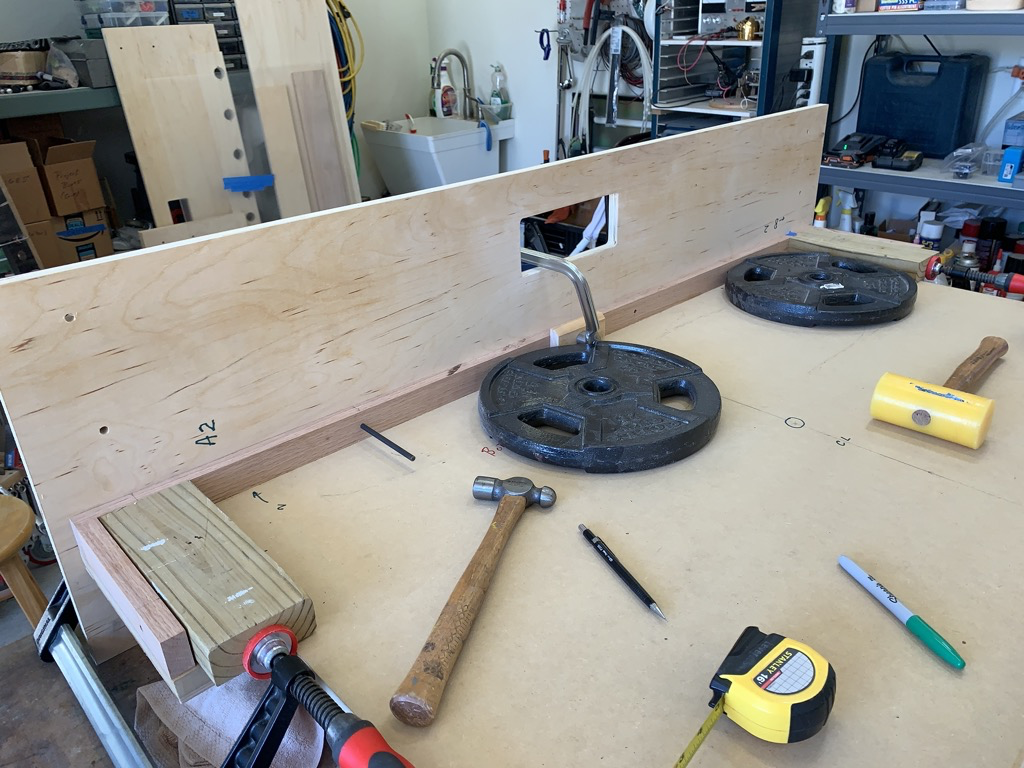
Image Gallery


This is awesome, the detailed drawings with dimensions are super helpful for foosball hardware projects, and the build quality looks fantastic!
Glad you like the info. We continue to enjoy ours.